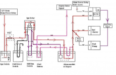
Don't know if you have one of these fitted Duck, but they have been known to cause trouble, worth looking if all else fails.
Tip over switch
It function is to cut-off power to the injection and ignition systems in case the machine is tilted too far from the vertical, too far meaning roughly over 65º inclination from the horizontal or indeed fall flat on its side completely.
Both the carbed and EFI models also have a mechanical tip-over valve in the tank breather system to stop fuel from spilling on the ground, see this thread if you want to know more about it:
http://www.triumphrat.net/twins-technical-talk/155943-gas-tank-breather-hints-and-tips.html
There's an added problem with the EFI models. The fuel delivery system, rather than working on just good old gravity feed, is forced by an in-tank high-pressure pump at as much as 3 Bars (46 psi) into the injector fuel rail. If, due to an accident, the fuel hose were to rupture or disconnect itself, the fuel would be sprayed all over the place and hot engine, possibly barbecuing the rider.
To avoid this dangerous situation the system has a device Triumph call a
"fall detection switch". It can also be referred to by various other names such as
"tip-over switch",
"bank angle sensor" and
"Vehicle Down Sensor".
Fuel injected cars also have one of these, usually called an "fuel cut-off switch" although as cars don't often tip over, the device operates following a heavy shock such as a crash, although I have known one to trip by banging the front wheel in a deep pothole. The shock stopped my wife's Peugeot and it wouldn't re-start until clever-Dick here remembered reading something about such a device and looked in the handbook to learn its location. It turned out to be a red rubber-covered lump with a button on top. Pressing down this button fixed things. Worth finding out where this device is sited under the hood in your car for future reference.
The sort fitted to bikes is auto-reset, that is, it returns to normal after picking the bike up.
Where is it?
On our Bonnies the switch is situated under the seat, held down by a couple of bolts and flexible rubber mountings. There must be something very important about this thing: The two M4 bolts are treated with semi-permanent red Loctite and very difficult to undo, and the whole thing is suspended by fairly sophisticated and pliable rubber mountings so that it's allowed to move about a bit and yet be impervious to vibration. The casing is moulded with the word "UP" in large letters to make sure you know which way it fits.
How does it work?
I have seen examples of similar devices on other bikes and they consisted of variable resistors or potentiometers with the wiper part of it mounted on a kind of pendulum. Reminded me a bit of those "tilt" switches fitted to Pinball machines.
Resistance varies according to the angle the bike is leaned while standing still. On the move however, centrifugal forces maintain the pendulum at the same upright position no matter what the angle of lean is. Some sport bike heroes reckon they can lean so much that the tip-over switch can't keep up with their cornering prowess but this is crap...a sort of urban myth. The reality of those centrifugal forces keeping the pendulum straight doesn't stop them from by-passing the switch in all manner of ways, some substitute it for some resistors, others dismantle and fix the pendulum by stuffing the thing with silicon sealant, etc.
On ours I believe there are two resistors inside plus also some sort of pendulum and contacts, (you can feel the pendulum moving about if you shake the switch in your hand). The resistors appear to be arranged as a voltage divider as shown in the circuit diagram below. I don't yet know how the contacts are arranged internally.
The ECU sends a +5.0 Volt signal down the pink/silver wire, the pink/black wire is connected to ground or negative. The ECU then receives back the signal resulting from the internal voltage divider through the pink/blue wire. This signal can range from 0.4 to 1.4 Volts. (on my particular bike I get 0.65 Volts). As the switch and therefore the bike, is tilted this output signal remains steady until such time as the switch is around 65º from its normal horizontal position. The output voltage then changes abruptly to something like 3.7 to 4.4 Volts, (on mine it's 4 volts). As soon as this happens the ECM turns off cutting fueling and ignition with it.
What can go wrong with it?
Basically the device can either go open circuit internally or disconnected through a broken cable and send a no-volts signal to the ECU, or it can get "stuck" or faulty and send a "bike tipped-over" high-volts signal to the ECU even though the bike is upright.
In both cases the engine MIL (Malfunction Indicator light) comes on, but the engine will only stop if the high-volts condition happens. This is because the ECU can't differentiate between a real fall or a faulty switch so it plays it safe and stops things.
An OBDII hand-held scanner or diagnostic software such as Tuneboy, DealerTool or our beloved TuneECU, can clarify what the fault is and enable us to turn the MIL light off once the fault is cleared.
It will show either:
Fault code
P1631 "Fall detection switch low voltage"
Fault code
P1632 "Fall detection switch high voltage"
What to do if I suspect a "high voltage" fault condition has stopped my bike without it falling over?
Remove the seat, locate the switch and, pulling the retaining clip outwards, pull off the connector. The engine should now run although the MIL light will remain ON.
Note that if you do really tip the bike over, the MIL light will also come ON although once you pick-up the bike the engine will operate as usual. The light will remain ON until cancelled and re-set, or the engine has gone through 3 full cold/hot cycles, when it'll go off by itself.
If you need to replace it the
part number is T2502405 and it costs £39.79 ($63.51).
Can it be by-passed altogether?
Yes. Not advisable due to safety concerns, but as we've seen, simply unplugging it will allow the bike to work normally but the MIL light will remain on for all eternity. To turn it off we must provide the ECU with a similar level of voltage signal that it would be receiving from the device if it was still fitted and wired in, something in the range of 0.4 to 1.4 volts.
A suitable pair of resistors can be calculated to provide that signal by installing an external voltage divider. I'm crap at calculating things, so I've measured the actual resistances that the device was giving me and simply tried it with a couple of very similar value resistors and it works. Bike starts and runs OK and no MIL light.
This last photo shows the values of resistances, wire colours and voltages to be expected for future fault-finding. These are:
Connections top to bottom:
Pink/silver...... +5 Volts
Pink/blue........ signal output of sensor to ECU. Normal upright position gives 0.65 volts. Tipping over 65º changes this abruptly to 4 volts.
Pink/black....... ground or negative.
Resistances:
Between pink/silver and Pink/blue 3.88 Kohm
Between Pink/blue and Pink/black 15.5 Kohm
Between Pink/silver and Pink and black 19.35 Kohms


